Data Acquisition Guide
Regardless of the technology you employ, acquiring aerial photographs for Melown Photogrammetry requires planning. The better the dataset, the better result you get. Conversely, datasets covering the same area can differ vastly in terms of processing cost.
This guide explains how to shoot a good and cost-effective dataset for true 3D mapping. If you have done photomapping surveys before you might want to go straight to our flight calculator.
What are the requirements on input datasets?
The input for Melown Photogrammetry consists of the following data:
- a set of uncalibrated aerial images,
- camera GPS position in the EXIF of each image,
- a set of ground control points (optional),
- additional parameters such as autofocus information and area of interest.
Planning the flight
The following is an overview of things that affect the flight plan.
Camera resolution
Camera resolution is the size of the image taken by the camera, in pixels. Higher resolution leads to more detailed 3D models and may also allow flying in higher altitudes.
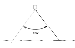
Camera FOV
The angular extent of the scene captured by the camera is called the field of view (FOV). The field of view affects the number of images that need to be taken, the directionality of the data (see below) and the ground sampling distance.
Ground sampling distance (ground resolution)
The ground sampling distance (GSD) is the distance between adjacent camera pixels measured at ground level. A dataset is said to have 10 cm GSD if the image pixels are, in reality, 10 cm apart on the ground. GSD is often called “ground resolution” by the general public.
Flight altitude
The flight altitude affects the GSD and vice versa. In fact, the four parameters camera resolution, camera FOV, GSD and flight altitude are closely related. Any three parameters determine the fourth one.
For example, given camera resolution, FOV and desired GSD, one can calculate the optimal flight altitude. Or, with fixed camera parameters and the flight altitude, is it possible to calculate the resulting GSD.
Overlap and sidelap
The 3D mapping algorithm needs to see each point in multiple images to create a 3D model. The images thus need to overlap. Higher overlap means higher certainty and accuracy of the computed geometry.
Assuming that the images are taken in a regular grid, there are two kinds of overlap. Overlap in the direction of flight is called forward overlap (or route overlap). Overlap between neighboring rows of the grid is called sidelap (or transverse overlap).
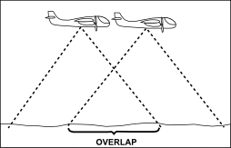
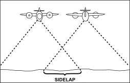
A dataset for true 3D mapping needs to have significant forward overlap as well as sidelap. Both are quantified as percentage of image width or height.
Directionality
In surveys intended for DSM or orthophoto mapping it is sufficient to capture level surfaces such as roofs of buildings. However, true 3D models can be viewed from any angle so it is important to capture virtually all visible surfaces, including walls and facades. Any object in the area of interest should be photographed from the top and at least four other directions, multiple times.
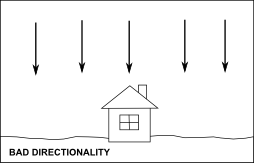
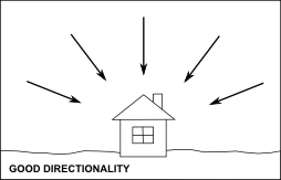
The directionality of the dataset can be improved by increasing camera FOV or by including oblique images.
Oblique imagery
There are two types of aerial photographs:
- vertical - the camera axis is perpendicular to the ground, i.e. camera points to the nadir,
- oblique - the axis of the camera is tilted away from the nadir. Oblique images typically supplement vertical images and can greatly improve directionality of the dataset. It is easy to obtain virtual FOVs as high as 120 degrees.
However, the offset from nadir for oblique images should not be excessive. Areas that are too far from the camera are useless for computation and there is no point in including the horizon in the images.
Virtual FOV
Oblique images, if present, typically exist in all four directions around each vertical image. Each such group can then be thought to form an output of a virtual camera with a higher FOV. We call this extended field of view the “virtual FOV”.
For vertical only datasets the virtual FOV is the same as the real camera FOV.
Camera orientation
The camera can be mounted so that the top side of the image is facing forward or sideways. The former approach is more economical as it allows sparser flight lines at equal sidelap.
True 3D requirements
There are two basic requirements on datasets intended for true 3D mapping:
- each geographic point to be triangulated should be visible in at least 32 images,
- the virtual FOV should be at least 60 degrees to ensure sufficient directionality. If only vertical images are present, the first requirement directly translates to the required image overlap: both forward overlap and sidelap should be at least 83%. If oblique imagery is involved, proper grid spacing can be determined using our flight calculator.
DSM/orthophoto requirements
Many aerial surveys to date have not been planned with true 3D in mind. Lesser requirements exist to produce digital surface models (DSMs) or orthoimagery:
- each geographic point needs to be visible in at least 8 images,
- there is no requirement on FOV since directionality is irrelevant to DSM. Vertical only datasets suffice for DSM or orthophoto mapping and the above 8 images requirement translates to 65% required overlap/sidelap. This may not seem like a big difference from 83% needed for true 3D but in reality it means 4x fewer images.
Quality reports
Melown Photogrammetry creates a preliminary quality report after initial processing of a dataset. The report contains visualizations of overlap and directionality and can be used to check which parts of the dataset satisfy requirements for true 3D mapping.
An example quality report is provided on this website.
GPS positions
The EXIF tags GPSLatitude, GPSLatitudeRef, GPSLongitude, GPSLongitudeRef, GPSAltitude and GPSAltitudeRef need to be provided in all input images (for reference see following link).
GPS readings are used to approximately position the 3D model. Consumer grade GPS is sufficient.
Ground control points
If the reconstruction is supposed to serve for metric measurements or if it needs to align precisely with other geographic data, ground control points are required.
A ground control point (GCP) is a point that can be accurately identified in the images and whose precise geographic position is known, including the altitude. These can be corners of buildings and sidewalks or any other feature whose pixel position is easily measured and whose real world position is known from an external source.
Once you identify the GCPs, just create a simple text file with one GCP per line. Each line will contain the filename of the image, the pixel position of the feature (may be fractional), the geographic position in the target coordinate system (e.g. UTM) and the MSL altitude.
Here is an example of a GCP file:
  # (this is a comment)
    # image path                   pixel x, y  geographic x, y, altitude
    camera1/0001_063000_2838.tif   5492 2445   651780 6860530 56.956
    camera1/0001_063000_2839.tif   5567 4010   651780 6860530 56.956
    ...
The GCP file is optional.
Additional parameters
The following are important parameters that are required in addition to all above:
- Autofocus information. Autofocus should be off as a policy. At any rate, it is critical that we know whether the camera had autofocus on or off.
- Area of interest. A larger area is usually photographed than that actually needed. A list of geographic points forming a polygon around the area of interest is useful.
- Target coordinate system. The 3D map is produced in an orthogonal projection of your choosing. We accept spatial reference definitions in the OGC WKT and PROJ.4 formats.